Peoria sits on a complex stack of glacial till, loess, and Illinois River alluvium that shifts dramatically within a few hundred feet. Borehole data from the Illinois State Geological Survey shows sand-and-gravel lenses interbedded with clay-rich diamicton at depths of 15 to 60 feet across much of the city, creating real challenges for resistivity interpretation. Our lab team has run dozens of vertical electrical sounding lines from the bluffs near Grandview Drive down to the riverfront industrial corridor. Each profile maps how resistivity changes with depth, flagging water-saturated gravels, clay aquitards, and bedrock contact zones before a single excavation starts. In a city where the water table often sits within 10 feet of grade, the CPT test can pair pore-pressure data with resistivity logs to confirm layer boundaries and reduce drilling uncertainty on tight urban sites.
When the VES curve drops 60 ohm-m in a single spacing step in Peoria, you are usually hitting a water-charged sand lens, and that lens will change your dewatering plan.
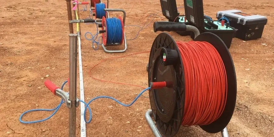
Local geotechnical context
The equipment chain starts at a 12-volt deep-cycle battery feeding a current transmitter, pushing square-wave DC through two stainless-steel stakes into the ground. The potential electrodes pick up the voltage drop across a known distance, and the meter calculates apparent resistivity in real time. In Peoria’s wet spring conditions, contact resistance at the current electrodes drops to a few hundred ohms, which is ideal. By August, the upper two feet of clay can dry out and crack, driving contact resistance above 5,000 ohms. We carry bentonite slurry and saltwater to wet the electrode holes when that happens, otherwise the transmitter cannot inject enough current and the readings get noisy. The biggest risk on a Peoria VES job is lateral heterogeneity: a buried sand channel parallel to the array can distort the 1D assumption and produce a false layer depth. Our field procedure flags any sounding curve that departs more than 15% from a smooth model, and we either reorient the spread or run a 2D resistivity line to resolve the geometry.
Quick answers
How deep can a VES survey reach in Peoria glacial soils?
With a maximum electrode spacing of 200 to 400 feet, the effective investigation depth ranges from about 100 to 200 feet, depending on layer resistivity. In Peoria’s typical loess-over-till sequence, we routinely resolve the bedrock surface at 80 to 150 feet. Deeper targets require a Schlumberger array and careful site layout to avoid cultural interference from buried utilities.
What does electrical resistivity testing cost for a residential or commercial site in Peoria?
A single VES sounding point typically runs between US$650 and US$910, depending on the maximum electrode spread and site access. A 2D resistivity profile with multiple electrodes costs more because of the longer field time and data processing. We provide a fixed-price quote after reviewing the site location, target depth, and any known subsurface conditions from nearby well logs.
Can you run resistivity surveys when the ground is frozen?
Frozen ground creates a high-resistivity surface layer that blocks current injection, making winter surveys difficult. We schedule most Peoria resistivity work between March and November. If a winter survey is unavoidable, we use saltwater pre-soaking at electrode positions and may switch to a dipole-dipole array to improve current penetration through the frozen crust.